The boundary layer, where drag and stall live
Back in the spring I wrote about the half of aerodynamics where air has no friction. That half is fast, it is accurate, and it gives you lift and pressure. It also cannot tell you how much drag a wing has, or when it will stop flying — which are, unfortunately, the two things a person choosing a wing actually wants to know.
This post is the other story. It is where drag lives and where stall lives, and it is where I have spent most of my time since. It is also much the harder of the two, for a reason that is worth stating at the outset: the outer flow and the film each need the other's answer before either one can start.
The film#
Everywhere except very close to the skin, air behaves as if friction did not exist. Very close to the skin, friction is the only thing that matters, because air genuinely sticks to solid surfaces. The molecules touching the wing are, on average, going exactly the speed of the wing. A tiny distance away they are going full speed.
Everything friction does to a wing happens in that gap.
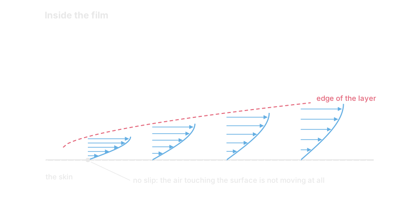
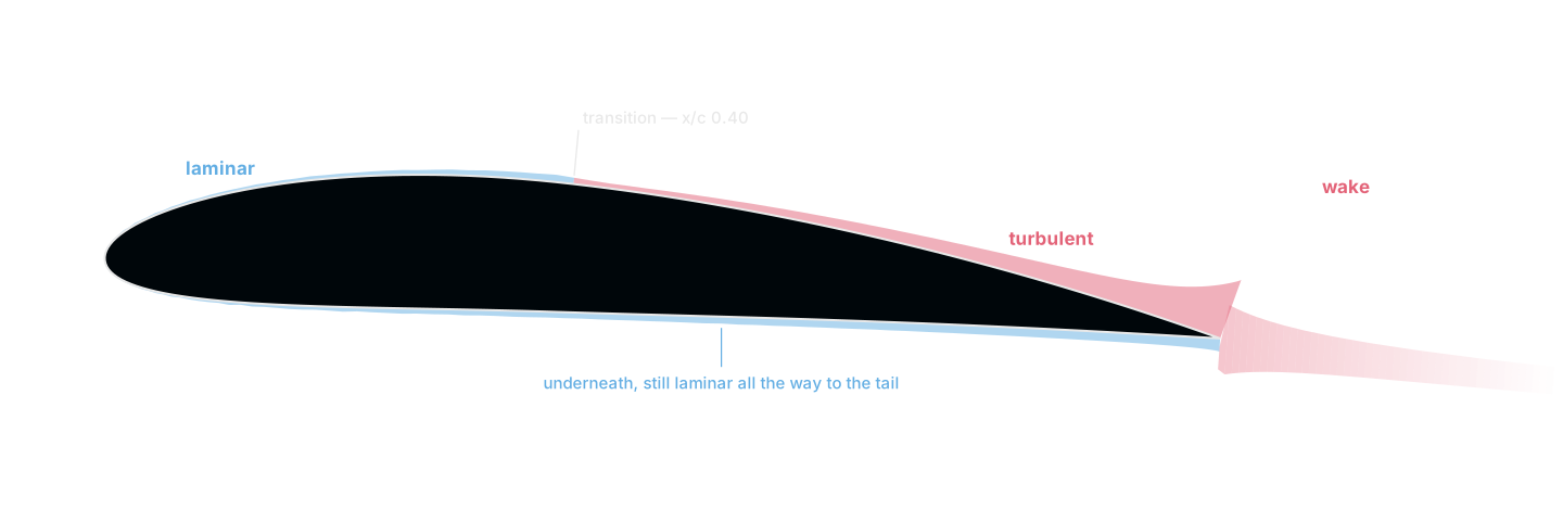
The gap is thin. On the section in the hero image at Re 10⁶ it is about one percent of the chord over most of the wing. That thinness is the entire reason any of this is tractable, because it means the outer flow barely notices the layer exists, and the layer can be solved as if the outer flow were simply handed to it.
Nobody solves the profile#
The obvious approach is to work out the actual shape of that velocity curve everywhere, which means solving a partial differential equation over a two-dimensional region for every case. People do this. It is called a Navier-Stokes solve, it takes minutes to hours, and it is not what I want when the point of the project is to sweep a hundred candidate sections.
The trick, and it is a very old one, is to stop caring about the shape of the curve and keep only two numbers per station: how much air is missing, and how much push is missing.
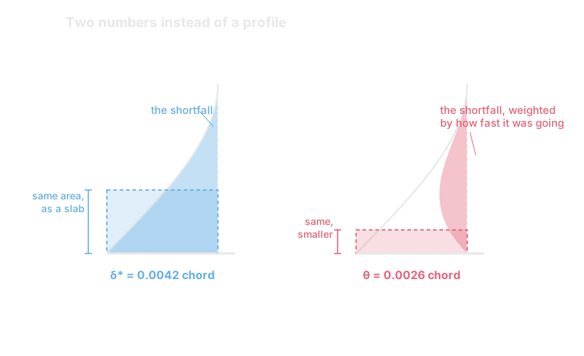
δ*, the displacement thickness, is the first. Add up the air that failed to arrive because of friction, and ask how far out you would have to move the wall to lose that much air from a flow with no friction at all. That distance is δ*. It is the number that matters most here, because it is the only thing about the boundary layer that the outer flow can see: as far as the frictionless solve is concerned, the wing is simply δ* fatter than it really is.
θ, the momentum thickness, is the second. Same idea, but weighting each bit of missing air by how fast it was going. This one is the drag, more or less directly — momentum that the air had at the front and does not have at the back went into the wing.
One number decides everything#
Their ratio, H = δ*/θ, turns out to be the interesting one. It says nothing about how thick the layer is and everything about its shape — specifically about how full the profile is near the wall, which is to say how much momentum the flow has left down there to keep pushing itself along.
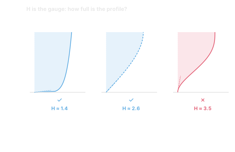
A turbulent layer runs at H ≈ 1.4. It is constantly dragging fast air down from the outside and slinging slow air up, which keeps the wall region energetic — at the cost of far more skin friction. A laminar layer sits around 2.6: much slicker, much less able to cope with anything difficult.
And when the flow is asked to climb into rising pressure — which is exactly what the whole rear half of an aerofoil asks of it — H climbs. Somewhere around 2.4 for a turbulent layer, and nearer 3.5 for a laminar one, the profile runs out of momentum at the wall, the flow stops, and it lifts off the surface. That is separation, and it is the mechanism behind stall.
So the entire drama of a wing section is: how long can you stay laminar (cheap, but fragile), and having gone turbulent (expensive, but tough), can you get to the trailing edge before H runs away?
Waiting for a wobble#
The switch between the two is called transition, and it is the single most consequential thing in the whole model, because it decides both the drag and the toughness.
It is not a threshold you cross. A laminar layer is unstable long before it is turbulent: a tiny disturbance at the right frequency grows, exponentially, as it travels downstream. The model I use — the e^N envelope, from Drela and Giles — integrates that growth along the surface and declares the flow turbulent once the most-amplified disturbance has grown by a factor of e^N.
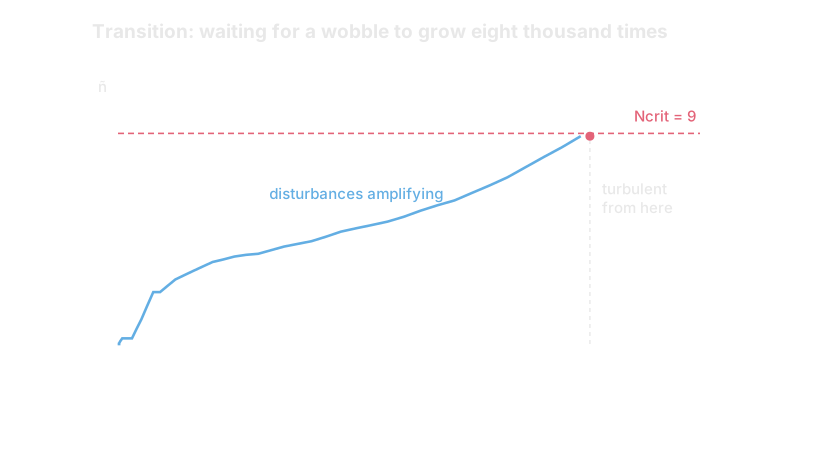
The obvious cheaper alternative is Michel's criterion, which is a local correlation: look up the state at this station, ask whether it has tripped yet, forget everything else. It is consistently wrong here, firing 0.1 to 0.2 of chord too early across Re 2×10⁵ to 10⁶ and costing about five points of mean drag error. The reason is the whole point of the previous paragraph. Amplification has memory. A lookup does not, and instability is a thing that accumulates.
Drag, at last#
With a laminar run, a transition point and a turbulent run, you can finally compute a drag that means something. The route is Squire and Young's, from 1937, and it is a lovely piece of accounting: take the momentum thickness at the back of the wing, and extrapolate what it would become infinitely far downstream, where the wake has finished mixing out and the pressure is ambient again. Momentum that never comes back is drag, so that far-downstream θ is the drag, up to a factor of two.
What that buys is the ability to ask where a wing's drag actually comes from, and the answer changes completely across the range you fly in.
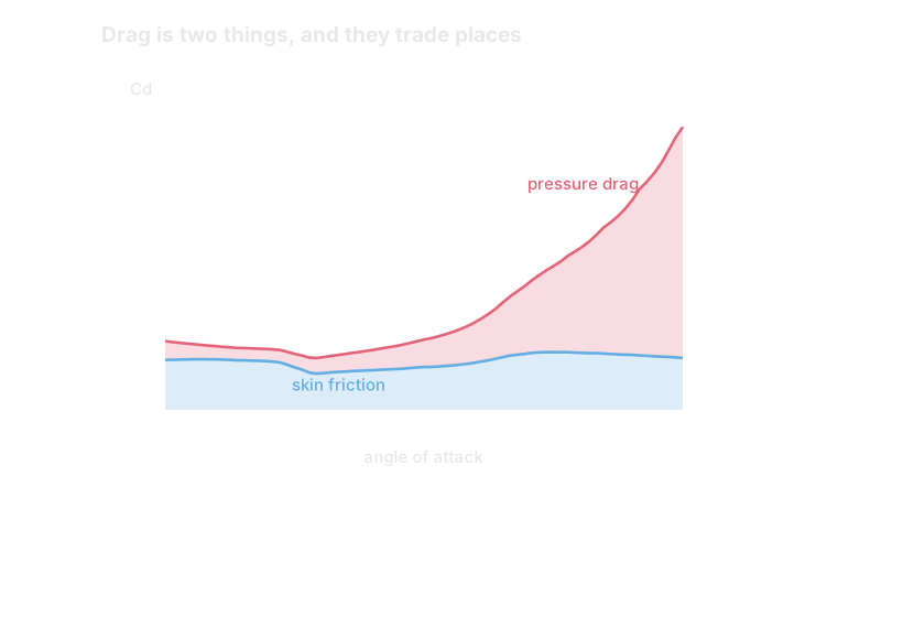
At small angles a wing's drag is almost entirely skin friction — the air rubbing along the surface, which is θ growing steadily along a well-behaved layer. That is the regime the whole integral method is comfortable in.
Push the angle up and skin friction barely changes, while pressure drag goes up by a factor of nineteen. Nothing is rubbing harder. What has happened is that the layer on top has thickened and begun to come away, so the outer flow can no longer close neatly around the back of the section, and the pressure on the rear no longer pushes forward as hard as the pressure on the front pushes back. That is the same d'Alembert cancellation from the last post, failing.
Two consequences worth carrying forward. The first is that a cambered section's least-drag angle is not zero lift — it is somewhere near the lift it was drawn for, because that is where the pressure distribution is gentlest on both surfaces at once. The second is that Reynolds number moves all of this, and not always the way you would guess. Drop a NACA 0012 from Re 10⁶ to 5×10⁵ and its least drag rises from 0.0054 to 0.0062 — even though transition slides aft, from 0.69 to 0.79 of chord, so it is getting a longer run of the cheap kind. The friction itself is rising faster than the extra laminar run can save.
Go one step further down, to Re 2×10⁵, and something else appears entirely. Down there the laminar layer separates before it ever transitions, sits off the surface for a few percent of chord, goes turbulent in mid-air and comes back down. That is a laminar separation bubble, it is expensive, and it is the single hardest thing in this subject to predict. Everything in this post assumes the layer stays attached to the surface until it is good and ready to leave, and down there it simply does not.
The circular argument#
Now the awkward part. The boundary layer needs to be told the speed at the edge of the layer, which comes from the frictionless solve. And the frictionless solve needs to be told the shape of the body, which — because of δ* — depends on the boundary layer.
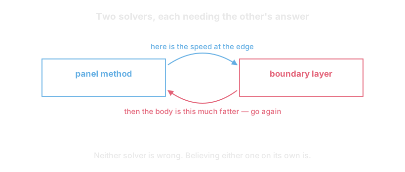
So you guess, and iterate. Solve the clean shape, march the layer, thicken the shape by δ* along the surface normals, re-panel it, solve again. Repeat until the two stop disagreeing. On the sections I have tried that takes between four and twenty-two passes, and the whole thing still runs in a few milliseconds, because the expensive part — factorising the influence matrix — is a couple of hundred rows and only has to happen once per shape.
This shape of problem — two models, each needing the other's output as its input — is worth recognising because it is not special to aerodynamics. What is specific here is that the loop has a hard edge to it, and the next two sections are about where that edge is.
The shape the air actually sees#
Here is what the coupling is doing, physically. At any real angle of attack the boundary layer on top of the section is much thicker than the one underneath, because the top is the surface being asked to climb the pressure hill. So the fattened body is not fattened symmetrically — it is fattened mostly on top, mostly at the back.
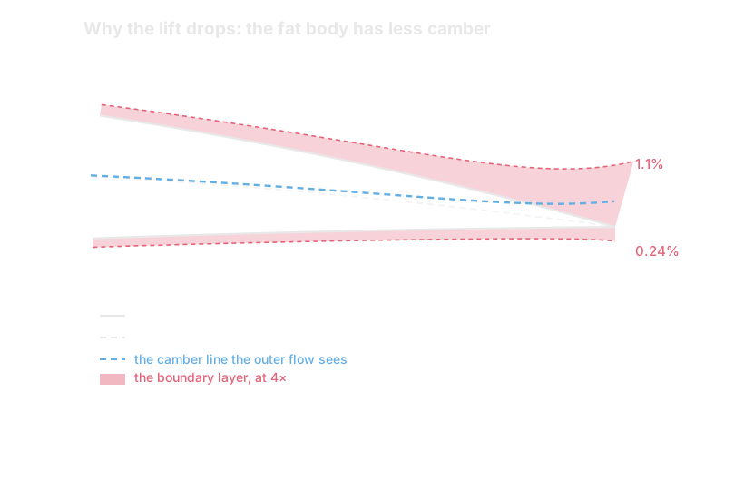
Which bends the effective camber line tail-up. Less camber means less lift, so the viscous answer sits below the frictionless one. That is viscous decambering, and it is the entire lift correction — the whole reason a real wing makes less lift at a given angle than the frictionless theory promises.
It also explains something that would otherwise look arbitrary. There is a fiddly detail in every scheme like this about what to do at the very back, where the displaced upper and lower surfaces have to meet at a single point again. It looks like bookkeeping. It is not: a bulge half a percent of chord deep over the last five percent of the wing reads to the outer flow as a small trailing-edge flap, and aft camber is disproportionately good at making lift. Get that closure wrong and you can move the lift by several percent in whichever direction your mistake happened to point.
Where the loop breaks#
That iteration works right up until the boundary layer starts to separate, and then it fails in a way that is worth understanding, because it is why the state of the art looks the way it does.
Marching the layer in direct mode means being handed the edge velocity and asked for the layer. As the flow approaches separation — as the shear at the wall approaches zero — that problem stops having a solution at all. Not a hard one: none. The equations become singular exactly at the condition you most want to resolve.
So a scheme like this has to be kept away from the edge, usually by clamping something on the way out of the march. The clamp is not physics, it is scaffolding, and it costs you exactly the region you would most like to be right about — because separation approaching the trailing edge is the onset of stall.
That is the honest limitation of the whole approach, and it is the reason the top of a lift curve is so much harder than the middle of one. The layer knows perfectly well that the flow is coming apart; the direct loop has no way of letting that news reach the lift.
What this cannot tell you#
It is worth being as blunt about the limits here as the last post was about the inviscid ones, because this method is the workhorse of practical aerofoil analysis and it has a shape of failure you should expect.
It is excellent at attached flow. Give it a section running somewhere in the middle of its range and it will hand you a drag figure good to a few percent, a transition location, and a lift corrected the right way by the right mechanism, in about a millisecond. That is a genuinely remarkable thing to get for the cost.
It is at its worst in exactly two places, and they are the two places that decide whether a wing is any good.
The top of the lift curve, for the reason in the section above. A method of this kind will tend to go on making lift past the angle at which the real section has given up. That is not a conservative error to have — a wing that never stalls on paper is very much the dangerous direction to be wrong in.
Low Reynolds number, where laminar separation bubbles appear and the assumption that the layer stays on the surface stops holding. Below about Re 5×10⁵ that is not a correction to apply, it is a different flow.
Both have the same root: the layer and the outer flow are being solved in turn rather than together. Fixing it properly means giving up the loop entirely and solving every boundary-layer unknown and every edge velocity as one system — which incidentally gives the wake behind the trailing edge somewhere to exist, and at the moment it has nowhere at all. That is a later post in this series.
Next#
Two posts in, there is now an instrument: shape and angle in, lift and drag and pressure out, fast enough to sweep. What there isn't yet is any way of knowing whether the section it just measured is a good one.
That turns out to be a much less obvious question than it sounds, and it is the next post — what a wing section is actually for, why there is no such thing as a good aerofoil, and the one budget that every trade in the field is paid out of.
Every number in this post came out of the committed reference data or the solver while I was writing it. If any of it is wrong, I would like to know.